A System-Level Approach to Combustion Efficiency and Draft Stability
Abstract
Energy consumption in glass manufacturing is predominantly concentrated in furnace operation. While significant attention has been given to burner design and refractory performance, airflow systems — including combustion air supply and flue gas extraction — remain comparatively under-optimized in many facilities.
This paper examines airflow behavior in glass furnaces from a system-engineering perspective. It discusses induced draft fan matching, pressure stability, resistance evolution, and coordinated control strategies. The objective is to outline a structured methodology for improving combustion efficiency, stabilizing furnace pressure, and reducing energy losses through airflow optimization.
1. Introduction
In regenerative and recuperative glass furnaces, combustion efficiency is strongly influenced by airflow dynamics. The furnace operates as a thermodynamic and fluid-dynamic system in which air supply, exhaust flow, and internal pressure must remain in equilibrium.
Airflow imbalance can result in:
- Flame instability
- Temperature non-uniformity
- Excess fuel consumption
- Increased refractory stress
- Batch material entrainment
Despite its operational significance, airflow management is often addressed reactively rather than analytically. Maintenance actions such as damper adjustments or fan replacement are frequently implemented without recalculating system resistance or reassessing operating points.
A system-level evaluation is therefore required.
2. Airflow Dynamics in Glass Furnace Operation
Airflow within a glass furnace can be simplified into three interacting domains:
- Combustion air supply
- Furnace internal pressure field
- Flue gas extraction via induced draft system
These domains are interdependent. Modification of one variable inevitably affects the others.
2.1 Furnace Pressure Sensitivity
Glass furnaces typically operate under slightly positive pressure conditions. Minor pressure deviations (±5–10 Pa) may alter:
- Flame geometry
- Heat transfer distribution
- Infiltration rates
- Crown temperature stability
Pressure oscillation is commonly linked to insufficient coordination between combustion air fans and induced draft fans, particularly in systems lacking closed-loop control.
2.2 Fan Operating Point Deviation
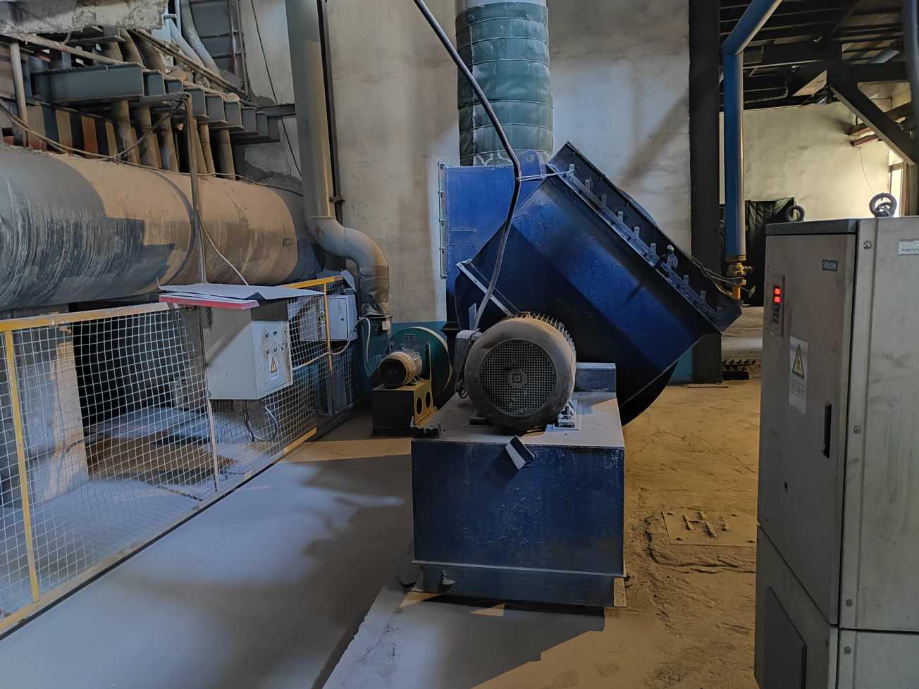
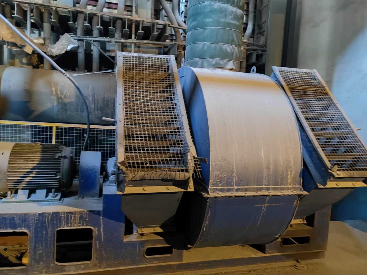
Centrifugal induced draft fans exhibit peak efficiency near the Best Efficiency Point (BEP). However, long-term operation frequently occurs outside this region due to:
- Resistance increase over time
- Production rate adjustments
- Improper initial fan selection
Operating far from BEP may lead to:
- Reduced aerodynamic efficiency
- Increased vibration amplitude
- Higher shaft load
- Accelerated bearing wear
From an energy standpoint, deviation from optimal performance curves directly increases motor power demand.
3. Evolution of System Resistance
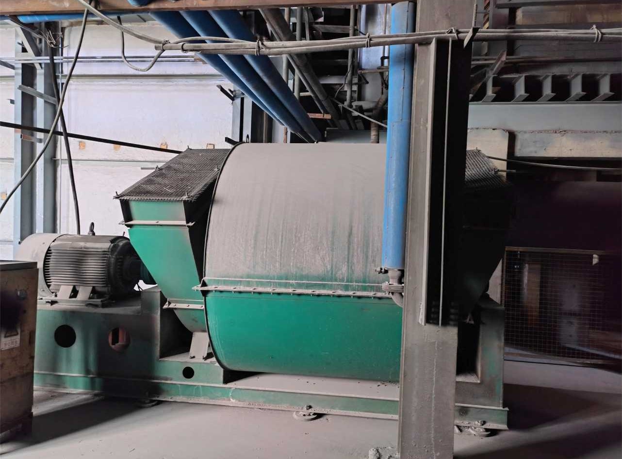
Airflow resistance in glass furnace duct systems is not static. It evolves due to:
- Particulate deposition
- Regenerator clogging
- Duct corrosion
- Seal deterioration
Failure to update resistance calculations during maintenance cycles results in persistent mismatch between fan performance curves and actual system requirements.
A periodic reassessment of system pressure loss is recommended, including:
- Static pressure measurement
- Flow verification
- Damper position analysis
- Leakage estimation
Such evaluation provides quantitative support for optimization decisions.
4. Methodology for Airflow Optimization
Effective airflow optimization requires an integrated methodology rather than isolated equipment modification.
4.1 Resistance Recalculation and Curve Re-Matching
The first step involves establishing an updated system resistance curve. The fan performance curve should then be superimposed to identify the real operating point.
Selection criteria include:
- Operation near BEP
- Adequate pressure margin (10–15%)
- Stable region of performance curve
- Stall avoidance
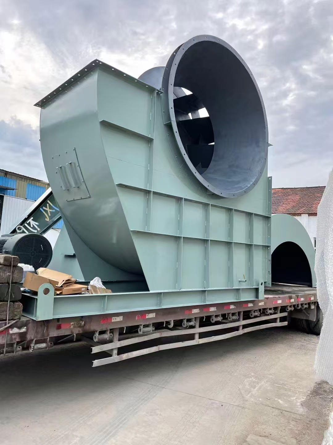
Backward-curved centrifugal fans are often suitable for high-temperature exhaust applications due to stable efficiency characteristics.
4.2 Variable Frequency Drive (VFD) Integration
VFD implementation allows dynamic adjustment of fan speed according to furnace load.
Benefits include:
- Reduction of throttling losses
- Improved pressure stability
- Lower mechanical stress
- Reduced partial-load energy consumption
Because fan power varies approximately with the cube of rotational speed, moderate speed reductions can yield substantial energy savings.
4.3 Closed-Loop Pressure Control
Advanced furnace systems increasingly adopt pressure-based control strategies rather than simple airflow control.
A closed-loop configuration typically includes:
- Furnace pressure sensors
- Coordinated control logic between combustion air and induced draft fans
- Real-time feedback adjustment
This approach enhances thermal equilibrium and reduces fluctuation-induced stress on refractory structures.
5. Energy and Operational Impact
Fan power requirement can be approximated as:
Power ∝ (Flow × Pressure) / Efficiency Thus, optimization can be achieved through:
- Reducing unnecessary excess airflow
- Lowering system pressure drop
- Increasing aerodynamic efficiency
Field evaluations in medium-capacity furnaces have demonstrated:
- 5–8% reduction in fuel consumption
- 8–15% reduction in fan motor energy use
- Improved combustion uniformity
- Reduced thermal cycling stress
While percentages vary by furnace design and operational condition, the trend remains consistent: airflow optimization delivers measurable efficiency gains.
6. Discussion: From Component Replacement to System Engineering
Replacing a fan without recalculating resistance rarely resolves underlying inefficiencies. Similarly, increasing airflow to compensate for combustion instability often exacerbates energy loss.
Airflow should be considered a dynamic subsystem within the broader thermodynamic structure of the furnace.
A shift from equipment-based thinking toward system engineering is essential. Optimization must integrate:
- Fluid dynamics
- Combustion chemistry
- Mechanical stability
- Control logic
Only through coordinated evaluation can sustainable improvements be achieved.
7. Conclusion
Airflow management plays a decisive role in glass furnace stability and energy performance. Although frequently categorized as auxiliary infrastructure, the airflow system directly affects combustion efficiency, pressure stability, and refractory longevity.
A structured optimization framework — including resistance reassessment, fan curve alignment, VFD integration, and closed-loop pressure control — provides a practical pathway toward improved furnace performance.
Future furnace efficiency strategies should therefore incorporate airflow system evaluation as a core analytical component rather than a secondary adjustment measure.